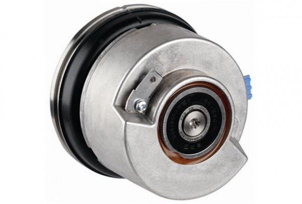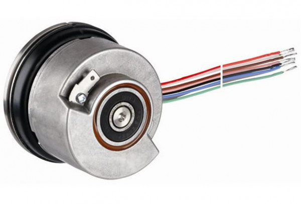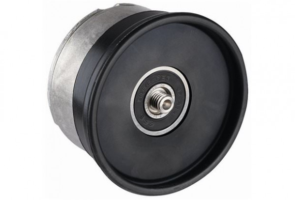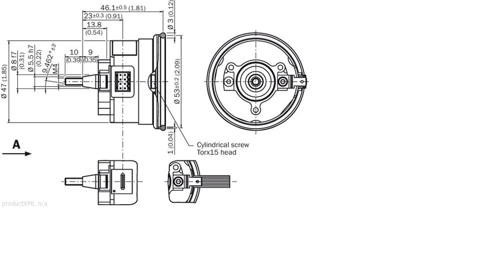
Ротационный датчик обратной связи SRS/SRM50 SRS/SRM50 - SRM50S-HEV0-K21 - 1051811 (sick148003)
Поставляем Ротационный датчик обратной связи SRS/SRM50 SRS/SRM50 - SRM50S-HEV0-K21 - 1051811 для промышленных и гражданских объектов. Оригинальная продукция с гарантией. Подбор аналога, доставка по Москве, СПб и регионам РФ.
есть на складе


наши менеджеры Online
Внимание!
Информация о товаре может быть неполной или требовать уточнения. Мы всегда готовы помочь — свяжитесь с нашими специалистами для получения актуальных данных.
Наши отгрузки


- Описание
Описание SRS/SRM50 - SRM50S-HEV0-K21 - 1051811
Safety-related parameters
| Safety integrity level: | SIL2 (IEC 61508), SILCL2 (IEC 62061) |
|---|---|
| Category: | 3 (EN ISO 13849) |
| Performance level: | PL d EN ISO 13849 1) |
| TM (mission time): | 20 a (EN ISO 13849) |
| Maximum demand rate: | Continuous (analog signals) |
| PFHD: probability of dangerous failure per hour: | 1.0 * 1E-08 2) |
| MTTFd: mean time to dangerous failure: | 1,073 a (EN ISO 13849) |
| footnote | 1) For more detailed information on the exact configuration of your machine/unit, please consult your relevant SICK branch office. 2) The values displayed apply to a diagnostic degree of coverage of 90%, which must be achieved by the external drive system |
Performance
| Number of sine/cosine periods per revolution: | 1,024 |
|---|---|
| Number of the absolute ascertainable revolutions: | 4,096 (Multiturn) |
| Total number of steps: | 134,217,728 |
| Measuring step: | 0.3 angular seconds at interpolation of the sine/cosine signals with e.g. 12 Bit |
| Differential non-linearity: | ± 7 angular seconds (Non-linearity within a sine/cosine period) |
| Operating speed: | 6,000 /min, up to which the absolute position can be reliably produced |
| Available memory area: | 128 Byte, 128 Byte (E2PROM 512) |
| Integral non-linearity typ.: | ± 45 angular seconds (Error limits for evaluating sine/cosine period) without mechanical tension of the stator coupling |
Механические параметры
| Flange type/stator coupling: | Rubber support |
|---|---|
| Dimensions: | See dimensional drawing |
| Moment of inertia of the rotor: | 10 gcm? |
| Maximum operating speed: | 12,000 /min |
| Maximum angular acceleration: | 200,000 rad/s? |
| Operating torque: | 0.2 Ncm |
| Start up torque: | 0.4 Ncm |
| Permissible shaft movement, radial, static: | ± 0.5 mm |
| Permissible shaft movement, radial, dynamic: | ± 0.1 mm |
| Permissible shaft movement, axial, static: | ± 0.75 mm |
| Permissible shaft movement, axial, dynamic: | ± 0.2 mm |
| Life of ball bearings: | 3.6 x 10^9 revolutions |
| Connection type: | Cable, 8-pin, radial, 200 mm |
| Shaft version: | Tapered shaft |
| Angular motion perpendicular to the rotational axis, static: | ± 0.005 mm/mm |
| Angular motion perpendicular to the rotational axis, dynamic: | ± 0.002 mm/mm |
| GEWICHT01: | 0.2 kg |
Электрические параметры
| Electrical interface: | HIPERFACE |
|---|---|
| Operating voltage range/supply Voltage: | 7 V DC ... 12 V DC |
| Recommended supply voltage: | 8 V DC |
| Output frequency for sine/cosine signals: | 0 kHz ... 200 kHz |
| Operating power consumption (no load): | 80 mA 1) |
| footnote | 1) Without load |
Interfaces
| Type of code for the absolute value: | Binary |
|---|---|
| Code sequence: | Increasing, for clockwise shaft rotation, looking in direction 'A' (see dimensional drawing) |
| Interface signals: | Parameter channel RS 485: digital, Process data channel SIN, REFSIN, COS, REFCOS: analog, differential |
Ambient data
| Working temperature range: | -30 °C ... +115 °C |
|---|---|
| Storage temperature range: | -40 °C ... +125 °C, without package |
| Relative humidity / Condensation: | 90 %, Condensation not permitted |
| Resistance to shocks: | 100 g / 10 ms / according to EN 60068-2-27 |
| Resistance to vibration: | 20 g / 10 Hz / 2,000 Hz / according to EN 60068-2-6 |
| EMC: | (according to EN 61000-6-2 and EN 61000-6-3) 1) |
| Enclosure rating: | IP 40 (according to IEC 60529), with mating connector inserted |
| footnote | 1) The EMC according to the standards quoted is achieved when the motor feedback system is mounted in an electrically conductive housing, which is connected to the central earthing point of the motor controller via a cable screen. This is also where the GND (0 V) connection of the power supply voltage is linked to earth. Users must perform their own tests when other screen designs are used. |
Почему заказывают у Евротехойл

Доставка до двери
Работаем с множеством транспортных компаний.

Тех. сопровождение
Полный подбор оборудования под Ваш проект

Готовые решения
Для множества отраслей (желательно переписать)

Высокая скорость
Обработка заявок и решений за один день
Вы недавно смотрели:
Арт: 120880
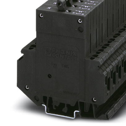
Термомагнитный защитный выключатель - TMC 1 F1 200 2,5A - 0914280
Производитель:
Phoenix Contact
Цена: по запросу
Арт: 779564
Мониторинг потокаКомпактные датчики контроля потока серии FCIC для установки в линиютранзисторный выход 24 В = PNP НО - FCIC-G1/4A4P-AP8-H1141/1.5
Производитель:
Turck
Цена: по запросу